Working Principle of an RFID System
An RFID System is composed of a tag and a reader. The reader generates and transmits an interrogation signal to the
RFID Tag. An
active RFID tag powers its microchip from a battery and transmits signal to the reader.
An RFID passive tag is powered by the reader either by magnetic induction (near-field coupling) or by electromagnetic wave capture (far-field coupling). Both of the methods can transfer enough power to a passive tag for sustaining its operation. RFID systems based on frequencies between 100 kHz and 30 MHz operate using magnetic induction. In contrast, RFID systems based on microwave frequencies (2.45 and 5.8 GHz) operate using electromagnetic wave capture.
Faraday’s principle of magnetic induction is the basis of nearfield coupling between a reader and a tag (Figure 1). An alternating magnetic field is created by passing large alternating current though the antenna coil of the reader. If the tag, incorporating a smaller antenna coil, is placed in this magnetic field, an alternating voltage appears across the coil of the tag. This voltage, once rectified and coupled to a capacitor, results in accumulation of charge, which is used for powering the chip of a passive tag.
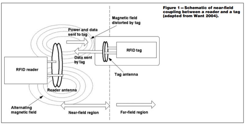
Data is transferred from the tag to the reader using load modulation. The tag varies the energy released from the capacitor to the coil of its antenna. This variation is transmitted from the tag to the reader by transformer-type inductive coupling. The reader reads the signal by monitoring the change in the terminal voltage of the coil of its antenna. Thus, changing the load resistance attached across the coil terminals of tag’s antenna has the effect of voltage amplitude modulation across the coil terminals of reader’s antenna. Near-field coupling is the preferred approach for implementing a passive RFID system.
However, the range of operation for a near-field RFID system approximates to c/2πf , where is the speed of light and f is the frequency of operation. This range is 3.5m and 0.05m for frequencies of 13.56MHz and 915MHz, respectively. As the frequency of operation increases, the range of operation decreases.
Therefore, near-field RFID systems operate at a frequency of less than 100 MHz. The magnitude of magnetic field is inversely proportional to the cube of the distance (r) from the center of the reader coil to the tag. If the strength of the magnetic field is too weak at a
given distance, the tag will not have sufficient energy to switch itself on. At 13.56 MHz, most near-field systems have a practical operating range between 0.01 and 0.30m. These limitations associated with near-field RFID systems have led to far-field RFID systems (operating at a frequency of greater than 100 MHz) based on electromagnetic wave capture.
-
Electromagnetic wave capture
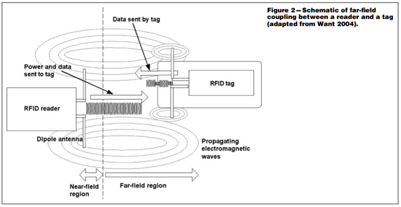
Far-field RFID system works on a principle similar to that of a radio set. Tags of far-field RFID systems capture electromagnetic waves propagating from the dipole antenna attached to the reader (Figure 2). A smaller dipole antenna in the tag receives this electromagnetic energy as an alternating potential difference. This potential difference is rectified and coupled to a capacitor for accumulation of charge and this is then used for powering the chip of apassive tag. The data of far-field RFID tags cannot be transferred to the reader using transformer-type inductive coupling because the tag operates beyond the near-field region. Instead, data is transferred from the RFID tag to the reader using back scattering. RFID Tags using backscatter reflect part of the electromagnetic wave sent from the reader, back to the reader. However, the tag can change the power of the reflected wave by varying the resistance of a load connected to its antenna. This variation in resistance of the load is controlled by the data to be transmitted. Thus, the power of the reflected wave received back at the reader is controlled by the tag’s data and is the mechanism for transmitting the data from the tag to the reader in a far-field backscatter RFID system.
In far-field RFID systems, energy delivered to the tag and signal transferred to the reader follow an inverse law. This attenu ates the overall signal strength by 1/r4 where r is the distance between the center of the reader coil and the tag. The range of operation (approximately 3 m) for a far-field RFID system is limited by the amount of energy received by the tag and the sensitivity of the reader to the reflected signal. With advances in the semiconductor industry, the energy required to power a tag at a given frequency continues to decrease. Inexpensive readers with improved sensitivity have also been developed.
To achieve longer range and operate tags with greater power consumption, backscatter tags often have a backup battery to supply power to the tag’s microchip. The tags generally have a power saving “power down” or “stand-by” mode to prevent the tag’s backup battery from being used unnecessarily. If the RFID tag moves out of the range of the reader, the tag automatically switches over to the “power down” mode. The RFID tag is not reactivated until a sufficiently strong signal is received in the read range of the reader, whereupon it switches back to normal operation. This backup battery of the tag never provides power for transmission of data between the RFID tag and reader, but serves exclusively for the supply of power for the tag’s microchip. Data transmission between the tag and the reader relies exclusively upon the power of the electromagnetic field emitted by the reader .


 Tel : +86 15814022871
 Email : sales@daftag.com